
🇹🇹 Free Delivery Nationwide 🇹🇹
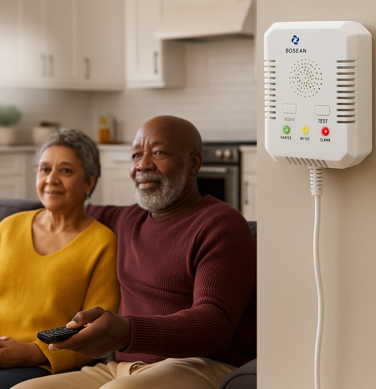
Carbon Monoxide +LPG Gas Detector
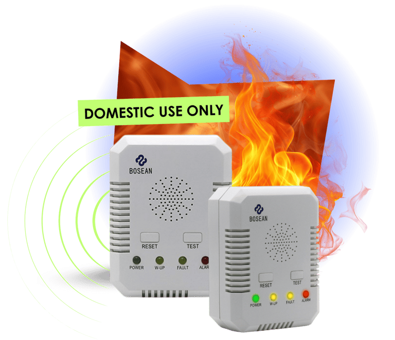
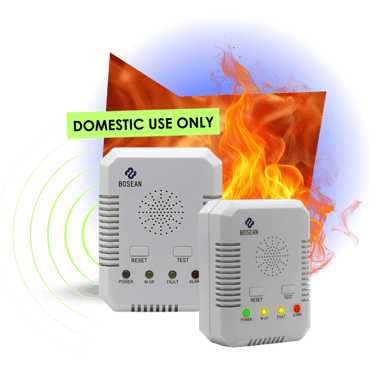
Smart Home Gas Safety System
Silent danger ends here: Detect leaks, detect CO, and shut off gas supply automatically.


How it works
Continuous air monitoring
This model is a wall-mounted and continuously monitors the surrounding air for both LPG (combustible gas) and CO.Immediate alarm when danger levels are reached
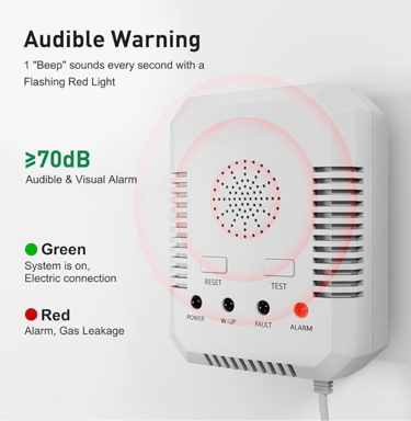
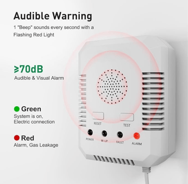
When gas concentration hits the preset thresholds (combustible gas: ~10% LEL; CO: ~100 ppm), the unit triggers an audible alarm (≥ 70dB) and visual alert.Automatic gas shut-off
Connected to a solenoid valve or relay output (optional) which interrupts the gas supply line instantly. While the official spec says “optional function … relay output NO or NC” you can configure it for automatic shut-off in LPG systems.Resume and reset
After the fault is cleared and the gas concentration drops, the sensor automatically resumes monitoring within ~30 s.


Dual detection: Combustible gas (such as LPG) and carbon monoxide (CO) (specification: combustible gas set-point at 10% LEL; CO at 100 ppm)
Wall-mounted for home use
Semiconductor sensor, natural diffuse sampling method
Response time ≤ 60 s, automatic resume ≤ 30 s.
Loud audible alarm ≥ 70dB, visual alert also present.
Specifications: AC 120 V power supply (important for installation)
Long life: rated 5 years under normal use.
★★★★★
Why Homeowners Love This System
Detect it way before disaster strikes
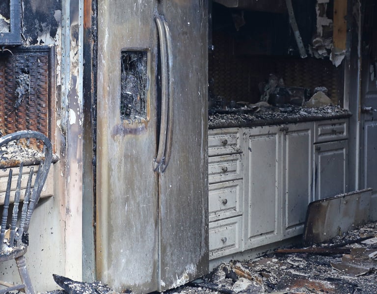
75 incidents in
3 years.
29 fires.
46 leaks.
One mistake can take a home.


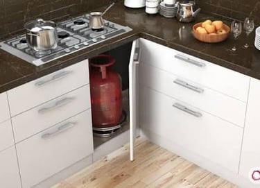
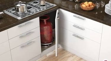
Ideal Locations & Use Cases
Kitchens
Especially with LPG cylinders/tanks
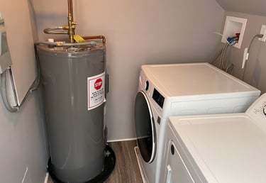
Laundry Rooms
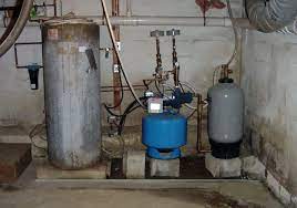


Enclosed Utility Rooms
Bedrooms
If gas-powered dryers/heaters are used
Or boiler rooms using LPG or gas
Adjacent to gas-powered heaters or near gas lines
Installation:
Step-by-Step


Step 1
Select an ideal installation location
For LPG detection: mount the unit within 0.3 m above the ground (as LPG is heavier than air)
Avoid mounting near strong drafts, windows, or direct air vents.
Maintain horizontal distance 2-4 m from cooker or gas source
Step 2
Power supply
Connect to AC 120 V power supply
Confirm the unit is powered and the display/LED is active.
Step 3
Install solenoid valve or relay if needed
Mount solenoid valve on the gas line feeding the appliance (ideally near tank/regulator).
Connect the relay output from the Detector to the solenoid valve wiring (NO/NC as required).
Ensure arrow direction of valve aligns with gas flow direction.
Step 4
Testing & commissioning
After full wiring, press TEST button or simulate low-level gas to ensure alarm triggers and valve shuts off.
Verify normal conditions resume once test is cleared.
Maintenance & checks
Replace after max ~5 years of use per spec to maintain reliability.
Periodically dust/clean sensor area, avoid blocking vents.
Check that solenoid valve remains functional (open/close movement) as part of routine safety audit.